Building a Quadcopter from scratch DIY : Part 1
You reached this page through some google search so I am assuming you already know what a Quadcopter or a Quadrotor is. Multirotors quite a thing these days and not a single tutorial is available on internet showing how one can build it from scratch. By scratch I mean from building your own pilot board, choosing your own sensors, building your own chassis and many more.
I am distributing this article into a few2 parts as there are so many things to cover in this tutorial. First part is going to be on mechanical section and assembly and others will be on Electrical and coding.
Lets list out the things you require to build this project :
4X BLDC Motors
4X Propellers
4X Electronic Speed Controllers (ESC’s in common term)
1X 1/4 inch square aluminium tube
1X Some IMU with accelero and gyro included atleast.
1X LiPo battery as per the requirement with higher value of C
1X Microcontroller to develop a pilot board.
1X Ultrasonic ping sensor
1X pair of any kind of transmitter receiver. (Prefer higher bps)
A bunch of wires, nuts and bolts of size 3, some misc components as we will go further with this guide.
And yes, a lots of tie clips, Tape, and double tape. Never forget that.
The Basics
Here is some basic concept about quadrotor. Quardrotor as the name says has 4 rotors which helps it to fly. As there are more number of motors involved it gives higher stability plus higher scope of maneuvering. Downside of it is it eats up too much of battery so its life is never more than some 10-15 minutes. Plus the components are way costly. So get into this project only if you are ready to invest around 10K Indian rupees.
There are two types of quadrotor configuration we may opt for.
(A) (A) (B)
| x x
| x x
(B)——-|——-(B) x
| x x
| x x
(A) (B) (A)
1. Plus Configuration 2. X Configuration
You can opt for either of them, its not much of difference, I prefer plus one as it is easier to code.
A quadrotor has four motors and to do the lift off it must produce a downward thrust. All motors revolving in the same direction may produce a downward force but it will also start rotating around its own axis as it the propellers will produce its own moment. So to avoid that and introduce stability we will rotate (As from the above configuration) A motors on clockwise and B on Anticlockwise direction. What it will do is, it will cancel the moment introduced. But now hey! two motors are producing downward and others upward thrust. It wont work either right? Yes! so to avoid that, we will Put reversed propeller on A motors and on B motors with normal ones. In market the propellers are available in such pairs only so you won’t be having any problem buying them.
The motors even though are rated at same rpm, are not that alike. So they will sure produce a slight imbalance to our drone. How to balance that? We have our sensors on board which will do the trick? How, I will explain it in a moment. Lets go for the construction.
The Construction of a chassis:
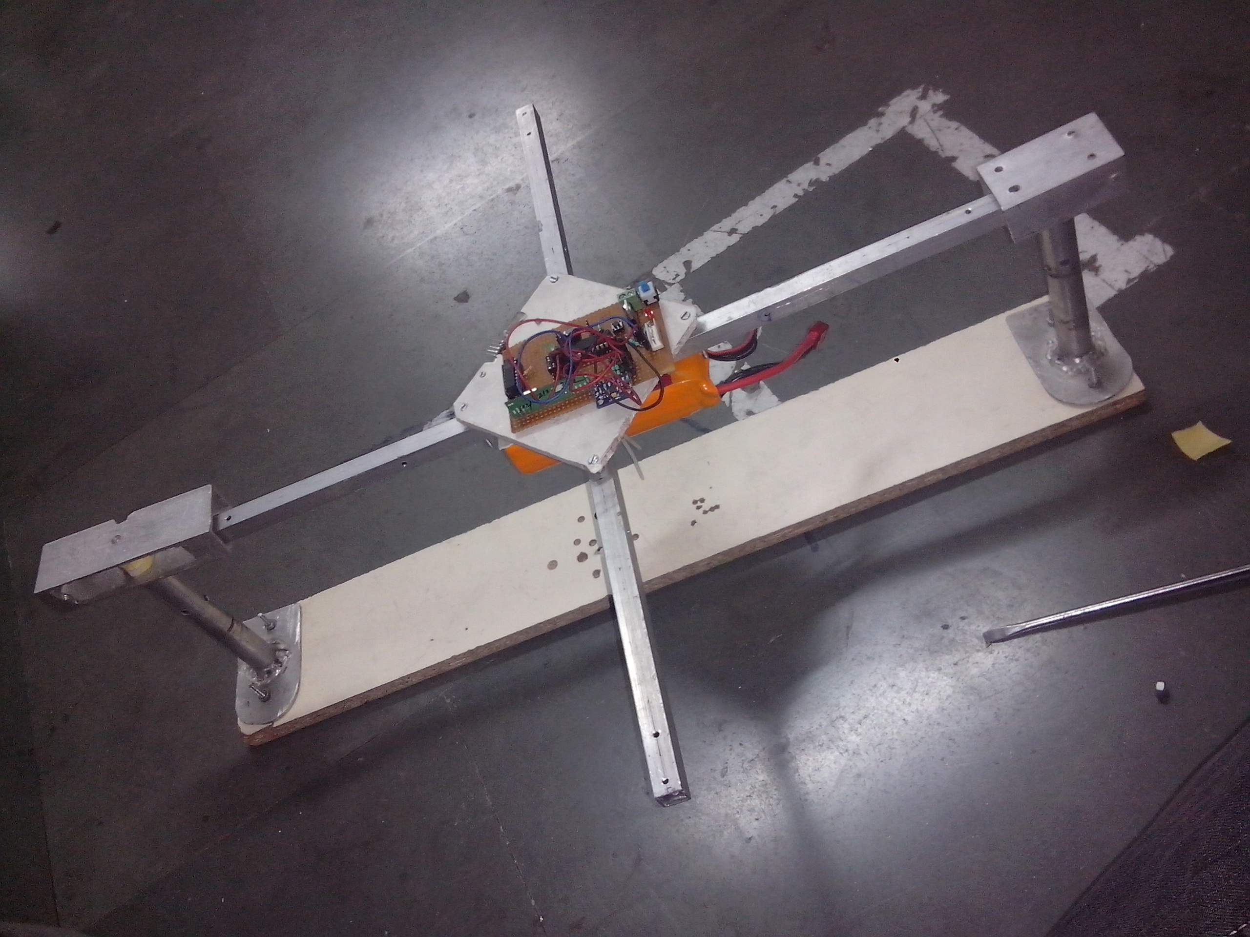
Decide the size of chassis you require for your rotor. Don’t make it too long or short. A middle ground you must achieve while deciding the length. Now cut the aluminium pipe you bought into such dimensions and weld it to each other for the desired cross shape.
You will need to drill on this chassis once you will get your motors and a cardboard or an acrylic sheet to mount your circuitry on.
The Motors and ESC’s:
Motors We are gonna use are BLDC ones. Why BLDC’s? because high power compact size and affordable(kind of). How do they work? There are like three windings around their core, each of them are excited through the ESC alternatively and through lenz law the core rotates.

The motor I have used is 1200KV motor. A KV rating means at single volt what its RPM is going to be. So as for a 12V supply a 1200 KVA motor will give
= 12 X 1200 = 14400 RPM.
The thrust we will get is given at the full scale reading at 12V in the datasheet. Our motor rated 740grams of thrust with 8X4 propellers. I will tell about the propellers later. Thus the total thrust we will get is
= 4 X 740 = 2960gms.
Divide it by half. and that much of weight it will easily lift.
so it is going to lift
= 2960/2 = 1480gms of weight.
So anything at that range your quadrotor will easily lift.
Now ESC’s. As the name suggests ESC’s are electronic speed control circuits. There are hall sensors, some power transistors, a microcontroller to monitor it all. We are not going in much detail of how these ESC’s work. We have to give pwm to these ESC’s and what they do is they adjust the supply to the motor and sources current to it.
Our motors were rated at around 12-13 Amperes at full load so anything above that level is considered safe. So ESC’s you use should be rated a couple of Amperes over the rating of your motor.

Take the marking for the holes of motor on the chassis. Keep the distance from the sensor exactly the same. Try to be accurate. Then Take the drills on the marking of size three. That is generally the size of the drills on the base motor. Now mount all the four motors on the chassis. Once done your chassis will look like this. Now mount the ESC’s also on the chassis as shown in the picture. Keep the distance same as the CG should lie exactly in the middle of the chassis. And the rotor should look symmetrical.
Propellers:
Yes without these your Quadcopter is not going to fly. As said earlier we need 2 complementary pairs of propellers for it to be able to fly. Propellers are available in different sizes. 10X3, 8X4, 3 blades, 2 blades etc. Longer the prop the speed will be more but thrust will be less and it will give more load on the motor. smaller will reduce the load. More the pitch of prop it will increase the thrust. So you need to adjust a sweet midpoint to obtain your prop by trail and error method. A 3 blade rotor is good if your motors have smaller kva rating.

Now propellers you cant just put on the shaft of your motor. You need to fix it on it right? For that there comes these coupling or caps for the propellers. Buy the appropriate size remove it into two parts. Put bottom one on the motors shaft then put propeller on it and put the other part on it and tighten the cap using the allen key.
Battery:
A regular sorts of battery won’t help in a quadrotor. A battery should be light in weight and it must allow the Motors to draw as much of 60A current without getting damaged. Thus lithium polymer batteries are our best bets. A regular lithium polymer battery will weigh around 200grams rating 11.1 with around 3AH rating. But for these batteries we must also consider the factor of C ( which is capacity according to my knowledge) under consideration. The battery I am having on my quadrotor is 3AH and 30C.
So it tells us that our rotor can take around 3 X 30 Amperes that is
=3 X 30 = 90A of current continuously without getting damaged.
As we have said earlier, Our motors are max rated at 15Amperes at full load. So in worst case condition the motors will be taking
=4 X 15 = 60A of current at max and around few mili amperes for peripherals. So we are in the safe limit.
Also 3AH rating means the battery can give 3A continuous and at that rate will last for an hour. but that isn’t a case here.
Our rotor consumes around 30Amperes while flying. So it brings our battery life to
= (3/30)*60 minutes = 6 minutes.
Yes you are right. A fully charged drone will only last for a few minutes. It isn’t the case for just my drone. The quadrotors generally won’t last above half an hour. So if you need hours of battery backup you must wait for a few years for the technology to come.
Thus ending the part one. Stay tuned for the next part.
P.S. I am very thankful to Mr. Swapnil Gawande for being a part of this project. Without him the part one of this tutorial wasn’t possible. Your inputs are needed mate.

How can I rotate two motors in clockwise direction and two in Anti clockwise direction?
Hi.
Your motors have three wires for input as they are bldcs. Your ESC’s are outputing three wires.
Now connect all the ESC’s to the motors. This will make your motors run in one direction.
Thats not we want right?
So now, from the motors you want to reverse the direction, interchange a couple of output wires on each ESC.
That will do the trick.