Building a Quadcopter from scratch DIY : Part 2
Previously on SkinnySatan…
We tried to tell you the mechanical structure, some basic concepts and some calculations regarding building of a quadrotor.
In this article, we are going to explain the electronic side and the Algorithm to make the quadrotor work.
Click here to check the last part
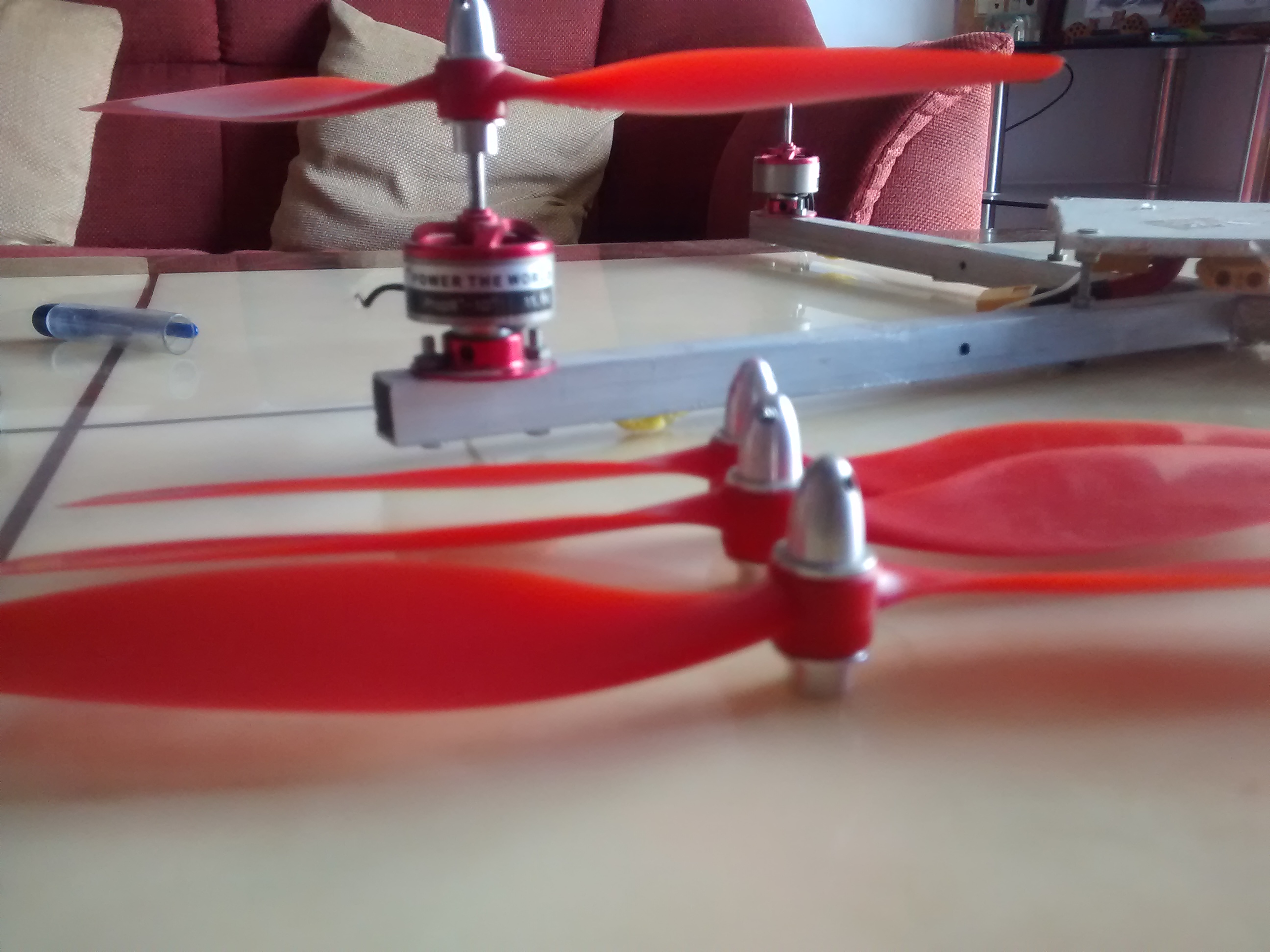
Assuming you are done with all the mounting parts and mechanical stuff.
This is now time to develop a control unit for your Quadcopter.
For that we are going to need a decent Microcontroller. And by decent i mean its going to need a few ADC pins, large enough memory. A handful of I/O’s, Atleast 4 PWM Outputs and also SPI/UART/I2C available on board.
Tl;dr buy an AVR or a PIC or ARM based microcontroller, these are usually available in market and very cheap, easier to implement.
I went for AVR because well, Atmel is love, Atmel is life. 😛
Don’t power it yet as we are going to take power from our ESC’s from their onboard regulator and it is good enough for common grounding.
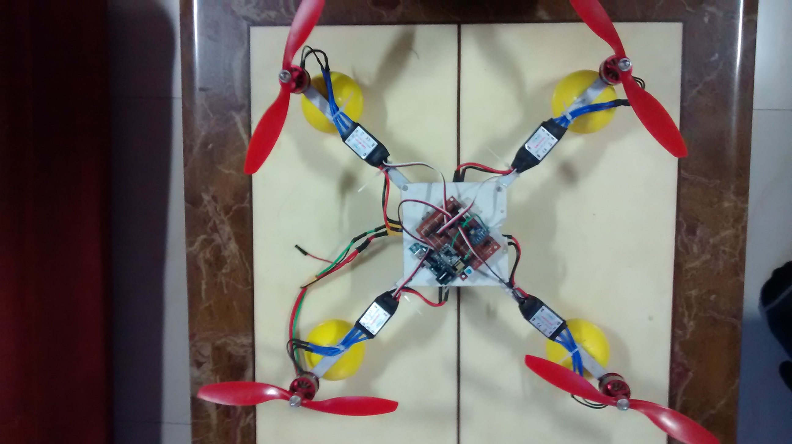
I am not going to give you an exact design for the board, just a basic idea and necessary stuff to build your own board.
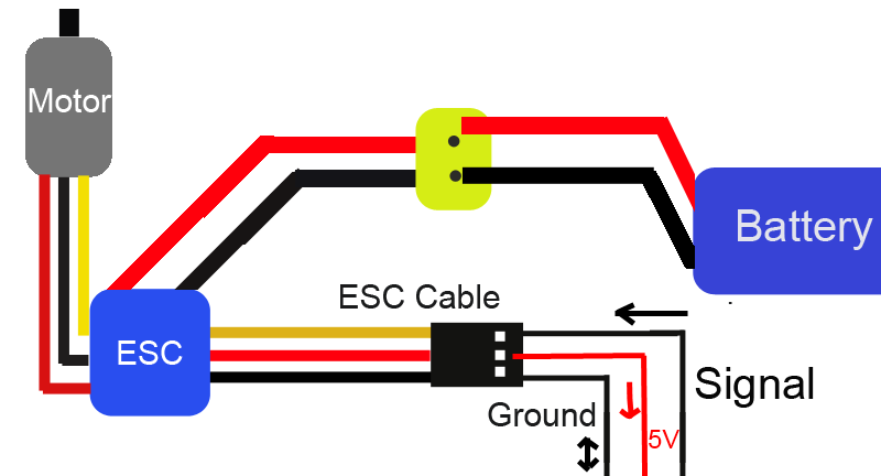
In the above diagram I have shown how the connections from Battery to the ESC are to be made. The other 3 wires, that are Ground, 5V and Signal are to be connected to the microcontroller.
Now you have got 4 ESCs and battery connections are same for all of them. for microcontroller connections, for 5V wire connect it from just one ESC to the microcontroller. Ground wires from all, tie them together and connect them to the ground of microcontroller.
The signal pins are to be connected to the PWM channels. So while making the connections write them down somewhere as you are going to need them while you are programming your board.
Now on paper, your Drone is ready to fly. But hey, how are you going to control it. You are going to need a Transmitter+receiver to send signals to board from your remote. A remote you can make using a simple RF pair as we have covered it in the previous articles. But then these are having a really low baud rate. (Just 1200bps) so if you are good with electronics, there are many cheap solutions available for this. You can go for a low range IR remote from your TV. Or use a Xbee pair if you have got enough money. NRF chips are also great solutions for this. This all depends on your skills. I will write a tutorial for this if I get time.
So from the output of the receiver you have built, connect it to the appropriate Communication channel.
Balancing the Drone.
The thing about the drone is, even if it will look symmetrical to your eyes, it isn’t and a slight variation in weight will easily topple and crash your Quadcopter. So to avoid this we are going to make the control a closed loop system.

By closed loop i mean, we just have to take feedback from our onboard sensors and in an appropriate way adjust the speed of motor.
For this sensor you need an accelerometer, and also a gyroscopic sensor if possible.
Accelero and gyro usually are tied together in a same unit called IMU. this unit, can be either communicated to the microcontroller by serial communication or ADC port. and from these values we can balance the Quadrotor.
I will help you to imagine this scenario. Lets say a Quadcopter is not neatly balanced and the weight is a bit more on right side. So even if all motors are on the same speed, the Quadcopter will start tilting on the right side and going rightwards. We don’t want this to happen in our ideal case. To avoid this we take our feedback from accelerometer. The right side tilt is measured by our accelerometer and is given to the Microcontroller to calculate the tilt in degrees. And accordingly the speed of right side motor is increased to balance out the tilt.
I hope you understand the scenario, if not leave a comment below. I will help you if you have any difficulties.
That is basically what is all needed to build a drone. You can also add a few more sensors like Ultrasonic to measure height, or a GPS to navigate this drone. Those thing you try including in your drone once your quadrotor starts flying.
So the basic Electronic part is done. Now the only part left to do is Programming and tuning/stabilizing.
Quadcopter Programming–
Arming the BLDC’s
Assuming you have appropriate programmer and Compiler to program your board. First part you need to check if your BLDC’s are getting armed properly.
A proper arming sequence is said to be necessary just to avoid abrupt starting of Motors. The signal provided to ESC is similar to the one for servo motors. Here is a tutorial to for servo operation.
the following code will help you understand the arming signal. Just give your ESC a full PWM initially, a little delay, then No PWM signal, another delay. and finally a little signal to get your motor moving.
#define MAX_SIGNAL 179

#define MIN_SIGNAL 18


Servo motor1;

Servo motor2;

Servo motor3;

Servo motor4;


void setup() {
  motor1.attach(3);

  motor2.attach(5);

  motor3.attach(6);

  motor4.attach(10);
motor1.write(MAX_SIGNAL);
motor2.write(MAX_SIGNAL);
motor3.write(MAX_SIGNAL);
motor4.write(MAX_SIGNAL);
delay(4000);
motor1.write(MIN_SIGNAL);
motor2.write(MIN_SIGNAL);
motor3.write(MIN_SIGNAL);
motor4.write(MIN_SIGNAL);
delay(2000);
motor1.write(40);
motor2.write(40);
motor3.write(40);
motor4.write(40);
delay(3000);
}
void loop() {
motor1.write(80);
motor2.write(80);
motor3.write(80);
motor4.write(80);
delay(100);
}
increase motor1.write(80); using your remote signals and you will see, even though your quadcopter tried to fly it is very unstable.
So to reduce that, we are going to introduce Accelerometer data to the controller.
PID Tuning:
For this we are going to use a PID equation to balance this out
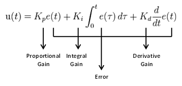
Here is how the above works.
kp=proportional constant;

ki=integral Constant;

kd=derivative Constant;
IDeal position= No tilt;

Current position= Some tilt;
Error= no tilt-some tilt.


add_error=add_error+Error;
Change_error=Prev_error-Error;
Adjustment=kp*Error+ki*add_error+kd*change_error;
Motor_speed=Motor_speed+Adjustment;
You can add the above code to almost everywhere, like in all of your applications.
(Adjust Kp to 0-1; ki to 0.009-0.0001; kd 0.01-0.09;)
You need to do the trial and error based calculations to implement a perfect one.

Now integrate the above pieces to all of your motors. And thats it. your Quadcopter is ready to fly. Have fun. Implement your personal ideas to it. And do tell me if you are working on something awesome.

that is so cool!! nice work!
Thank you 🙂
Loved your blog too.