Microcontrollers 101: Timers/Counters
Here We are, Starting an article series Micro controllers 101
We will be covering most of the stuff you will be needing in our upcoming articles. If you have any requests about our upcoming articles please do tell us in comments section
In this article we are going to cover Times, Counters and Waveform Generation using them.
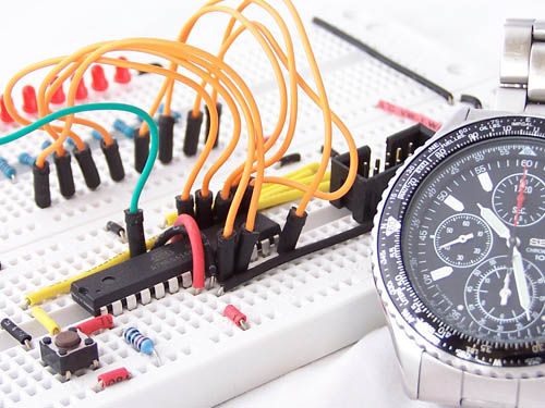
As you all know, we are huge fans of AVR Micro controllers, we will be demonstrating this stuff on atmega16 Micro controller which is a part of Atmega series and has almost everything inside it.
Timers :
Micro controllers are these clocked devices running on inbuilt clocks or external clock sources. And inside there is this guy called Timer who is there to measure these clock pulses. This is actually the counter guy in disguise. Which in this case is counting only clock pulses hence we are gonna call him Timer.
There are two types of timers in Micro controller 16bit and 8bit.
16bit counts to 65535 bits and thus great for higher resolutions.
8bits on the other hand counts only till 255 hence for lower resolution.

Timer when initiated will start counting the pulses till it overflows and resets again. Here is the trap. If the clock is very fast it is going to overflow very fast and generally that much of resolution we don’t want. Hence what we use is prescaler to scale down the output
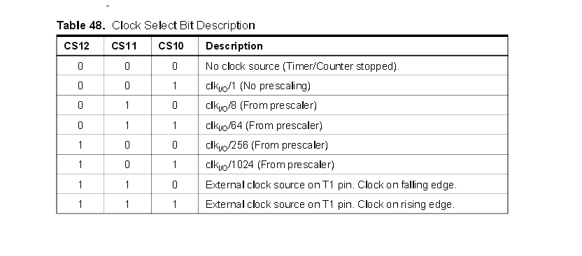
That is say if we use prescaler of 8, timer is going to count 1 pulse per 8 pulses.
Checkout the chart above to see different prescalers available.
The counted value will be loaded inside the register, in this case in TCNTx, x is the timer number refer datasheet.
Use this register as per your requirements and timing purposes.
example code Module :-
TCCR1B |= (1<<CS10); // Then start polling the TCNT1 thats all.
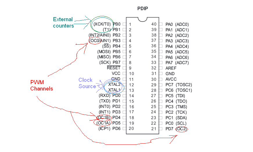
Counters : Now we have done counting and we need to count something external, like objects on conveyer belt from sensor or the ppr of an encoder, what we have to do here is in Above chart there is this option to count the external Source at the very end. Just turn it on and boom its gonna start counting your external objects. T1 or T0 are the pins as stated above are the people to whom you should join your countable input and output again will be stored to TCNTx peoples pockets.Simple right? Yes it is. 😀 Now go try it.
example code Module :-
TCCR1B |= (1<<CS11) | (1<<CS12); // Then start polling the TCNT1 thats all.
Now there are many more registers there we have not yet used of timers, what are they for. well there is one very important thing we yet to do which is PWM. We will cover it in next part of this Article.
