Microcontrollers 101: Pulse Width Modulation
Pulse width is like Heart of Micro controllers applications. We need them for like everywhere. From Driving the motors to dimming the lights. Check out our other blog posts to see how we have used PWM (Pulse Width Modulation) in our applications.
As we know our controllers as being digital buddies can understand and produce only 1s and 0s (+Vcc and Gnd). And say now we need 2.5V and we aren’t that rich to afford DAC’s.So PWM it is.
Now as we need 2.5V what it will do is at high speed it will switch between 0Volts and 5Volts so it will produce an equivalent pseudo analog voltage of same duty cycle of PWM.
Vout = Duty cycle X Vcc
In our micro controllers it takes help from Internal timer and with respect to it, it generates the PWM. We won’t be going deep in this stuff. Just we are gonna show you how to generate PWM in our very favorite AVR micro controllers.
As we have seen earlier there are two registers for timers TCCR1A and TCCR1B
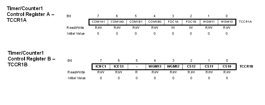
TCCR1A will decide what kind of waveform we want and TCCR1B will initiate it.
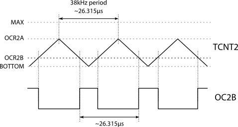
They both have WGM (Waveform Generation MOde) register which will decide the type of PWM. There are four bits and 16 choices. We like Phase and Frequency correct with ICR as top so we choose that.

Then here is COMxAx and COMxBx bits which will decide the OCR switching types. Choose any it wont really matter. except putting all 0’s it will disable PWM.
and the TCCR1B as we have seen in regular timers enable it and its configured.
Now you need to decide the frequency and Duty cycle.
there is this formula, use it to calculate value of ICRx and put the value in it.
ICRx= FCLK/2*N*freq
where N=1 or prescaler
and freq = frequency you want for your PWM
and Duty cycle you can calculate by putting the calculated value in OCRXa, OCRXb registers
OCR= ICR * Dutycycle/100
and that’s it you are done
here is how your code in configuration will look like
TCCR1A= 0b10100000;
TCCR1B= 0b00010001;
ICR1= 500; //10KHz Frequncy
OCR1A= 250; //50% duty cycle
OCR1B= 50; //10% duty cycle
refer our other codes for more operation details.
And yes you can shift the frequency and Duty cycle , Enable and disable it in real time using code so its really great deal.
Do the variations with different modes like Different timers, Fast PWM, different compare modes etc. Check it yourself. If you have got any doubts, Post in comments.
That’s all for today. Stay tuned for more stuff.

Thanks for this great info. I learned more about the comparator modes (COMxAx and COMxBx) from the site below: http://www.societyofrobots.com/member_tutorials/book/export/html/228. They stated the following:
0,0 – This PWM channel is switched off.
1,0 – This PWM channel is switched on in non-inverting mode
1,1 – This PWM channel is switch on in inverting mode