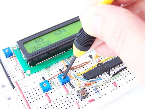
Microcontrollers 101: Analog to Digital Conversion
In earlier post about PWM we have seen our Digital buddies don’t understand Anything except 0’s and 1’s. And oh lets say we have here 2.5V as input here. Many sensors like gyros acceleros and many more produce only Analog voltage. Our micro controllers have a solution here. Analog to Digital Converters (ADC’s)
ADC has 3 step conversion method, Sample – Quantize – Encode
The precision of our ADC depends on the number of levels of quantization. Higher the bits of ADC more is the resolution.
General Atmega Micro controllers have 10bit ADC Channel which can give output from 0 to 2^10=1023 bits
Keep in mind for the given voltage, you don’t get voltage again. you get a number. That number will be your digital value. Also you can use your ADC till 8 bit also, by taking down the resolution. Read further to know how.
Here is the pinout for configuring ADC for Atmega16 micro controller
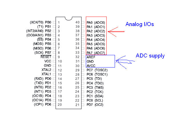
As you can see there are total 8 Analog pins. But we said earlier that there is only channel then how? Well they all are multiplexed internally to that channel. Nice isnt it?
Also for supply and noise immunity ADC has seperate Supply and Ground. The ground should be made common at only single point for reference grounding.
There are total 2 registers we need for configuring ADC. ADMUX and ADCSRA
ADMUX is for Adjusting reference voltage and choosing the channel.
ADCSRA is for configuraing enabling and starting conversion.

ADMUX has first 2 bits For adjusting reference voltages. Here is chart. Choose as per your requirement.
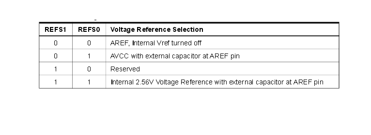
Here we will put it 01/ ADLAR is for Left or right adjusting. We will see its application later.
And the Mux pins are for choosing the channels. like 00000 will choose ADC0 pin 00001 for ADC1 etc. Also we can adjust the Gain for smaller signals. Refer datasheet for more details
ADCSRA is control and status register where
ADEN will enable ADC
ADSC starts conversion, this should be enabled in program operation.
ADIF is flag which tells us if the conversion is done, After starting the conversion we need to wait till this flag is set. then only take the result out otherwise it will give us wrong result.
ADPS are the prescalers. Ideal Value for Frequency is 250khz, so if your clock is too high do the math.
Remaining bits are interrupt related. Ignore them for now
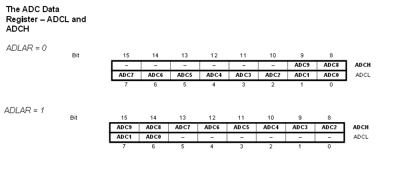
ADCH and ADCL are the registers which will hold our results for conversions. As we can see in this chart the ADLAR will decide the way the result can be hold.
Lets see a Demo Module of configuration:
ADMUX= 0b01100000;
ADCSRA= 0b10000000;
and here is how to poll the ADC converted value from the input analog voltage
ADCSRA |= (1<<ADSC);//Start conversion
while(!(ADCSRA & (1<>8));
temp16= temp16 | (ADCL<<8);//10bit result
You can change the channels by adjusting ADMUX in program.
ADC value obtained will be by this formula
ADC = (Vin*1024)/Vref (For 10bits Res)
ADC = (Vin*255)/Vref (For 8bits Res)
That’s all for ADC. Use it for your sensors or anything. Checkout our Skateboard Hand gestured posts code to see how we have utilized analog value from Accelerometer as a proof of concept.
Stay tuned for more stuff.
