Microcontroller 101: SPI and I2C/TWI with AVR
We saw in our earlier article some basics about UART protocol and you must know that That isn’t the only protocol we use for communication. UART is okayish for the one to one communication. but it isn’t that efficient when using a multi master multi slave bus.
Thus in this article, we are going to offer you some options for communication. Serial Peripheral Interface (SPI) and Inter-Ic-Communication (I2C. for that we try to go for some other protocols. One of them is SPI – Serial Peripheral Interface.
It is very simplistic protocol with one or many slaves. and slave need not be only a microcontroller, it can be memory,ADC,DAC etc. SdCard is a very good example of such slaves. And yes you can interface SdCard with such huge memory with your microcontroller. I will tell you how.
Lets first take a overview about working of this protocol.
SPI has 4 connections to be made between interconnecting networks on hardware side.
MOSI -- Master Out Slave In

MISO -- Master In Slave Out

SS   -- Slave Select

SCK  -- Serial clock

As you can see in the above diagram MOSI to MISO, MISO to MISO and SCK to SCK connections are done. and then the SS pins of multiple slaves are connected to multiple pins form master side and driven low whenever there is need to address that slave. Thus the slave understands that its their turn to communicate with the master.
At one time only one slave is to be addressed.
Implementation of SPI is similar to the UART, and very simple.
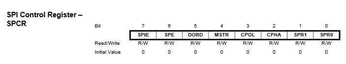
These are the registers to be Set to initialise the sequence.

For Master mode:
In SPCR (Control Register), Set SPE to 1 that is SPI- enable, Set MSTR indicating The Chip is the master, Data Order Clock Polarity and phase you don’t need to care about right now, as this is a test example.

SPR1, SPR0 and SPI2X (from SPSR Register) as the above table shows adjusts the frequency for SCK
void SPI_MasterInit(void)

{

DDR_SPI = (1<<DD_MOSI)|(1<<DD_SCK);

SPCR = (1<<SPE)|(1<<MSTR)|(1<<SPR0);

}
For Slave Mode: You Just need to set SPE to enable and that’s it. The Master will do all the hard work.
void SPI_SlaveInit(void)

{

DDR_SPI = (1<<DD_MISO);

SPCR = (1<<SPE);

}
While Transmission and reception similar to the UART communication Master puts data into SPDR, data register and waits for SPIF flag in SPSR register to show the transmission is done.
For slave, it will check if the SPIF flag is set or not, if set means the data is loaded to the slave, and it thus returns it to the processor.
void SPI_MasterTransmit(char cData)

{

SPDR = cData;

while(!(SPSR & (1<<SPIF)));

}
char SPI_SlaveReceive(void)
{
while(!(SPSR & (1<<SPIF)));
return SPDR;
}
Important things to note about SS pins:
SS should be held low if you are slave, and need to be addressed. If it is held high, SPI will reset and stop receiving the data.
If you are a master, set the SS pin to output or if input, hold it high. If it is held low, it will start to have insecurities, and consider himself as a slave. Thus starting to receive data instead of transmitting and abrupt termination of communication.
Here we have used SPI to one of our projects with bit-banging, you can try using the same logic by using SPI.
A Major Drawback for SPI communication is, if there are multiple slaves, to address those slaves, we need to get so many different I/O’s involved, increasing the hardware. Avoiding that, we will move forward to a bit complex method of communication.
Two Wire Interface (TWI) or I2C:
I2C also known as TWI, as the I2C is the trademark of Philips co. and can’t be legally addressed as I2C to market the product, and also as the name says, there are only 2 wires connected through out so the name, Two wire Interface. These are the required pins.
SCL- Serial Clock.

SDA- Serial Data.
SCL clock can be adjusted by the following formula
SCL_frequency= Fosc/((16+2(TWBR)*(2^TWPS))
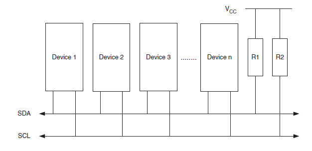
Note: While implementing, don’t forget to pull up both the SCL and SDA pins
In this mode of connection, you can connect 128 slaves to a single master without any problem. The data rate of TWI is really high, around fosc/4 for any master.
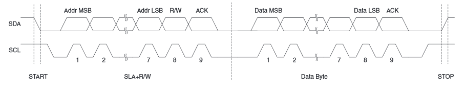
The physical addressing is not necessary in the I2C as the Address is set in the software in TWAR register. Also The Master includes the address in the data frame, so if the address matches to the Slave, Data is accepted and a feedback signal is sent back.
Registers necessary for setting up this are
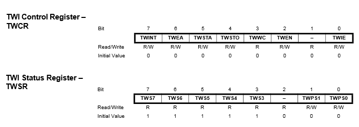
Here is how the whole transmission is going to happen.
1.Write a Start Condition in TWCR
TWCR = (1<<TWINT)|(1<<TWSTA)|(1<<TWEN);
2.Check Status code for sent Start condition
while(!(TWCR & (1<<TWINT)));
3.Check TWSR.
if((TWSR & 0xF8) != START)

ERROR();
4.Load SLA+W to the TWDR, Set TWINT to 1, TWSTA to 0.
TWDR = SLA_W;

TWCR = (1<<TWINT) | (1<<TWEN);
5.Status code indicates SLA+W is sent… BOooyeah!!!
while(!(TWCR & (1<<TWINT)));
6.Check TWSR for ACK.
if((TWSR & 0xF8) != MT_SLA_ACK)

ERROR();
7.Load data into TWDR and push it out.
TWDR = DATA;

TWCR = (1<<TWINT) | (1<<TWEN);
8.Check Status codes to check if sent.
while(!(TWCR & (1<<TWINT)));
9.Check TWSR for the ACK.
if

 ((TWSR & 0xF8) != MT_DATA_ACK)

ERROR()
10.Send Stop Condition.
TWCR = (1<<TWINT)|(1<<TWEN)|

(1<<TWSTO)
That was it. You can use the above samples to implement your own communication network with multiple slaves.
We will be posting another tutorial in using these protocols in actual communication. Stay tuned for that.
P.S.-> A really old article, it was stuck in drafts.
